T104 Wiring Diagram
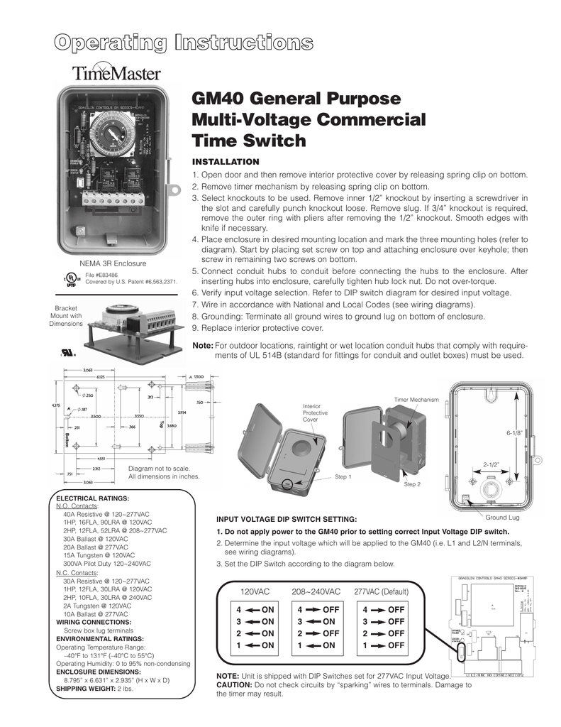
Grässlin uk ltd installation amp operating instructions. The chart and image above are correct for these models.

Intermatic T104 Wiring Diagram Wiring Diagram
Intermatic sprinkler timer wiring diagram.

T104 wiring diagram. Assortment of intermatic timer t104 wiring diagram. Use solid or stranded copper only wire. Wiring diagram 240 v 2 wire and ground clock motor:
Intermatic t104 pool timer off tripper turns the clock doityourself com community forums series 40 amp 208 277 volt dpst 24 hour mechanical time switch mechanism t104md89 indoor dial 208v 277v 2 poles wiring t104r won t turn pump on but does it guidance needed for of bypass in 240v system diy home improvement forum need help hooking… read more » Clock motor voltage and cycle must be as specified. Check out this guide to oven wiring problems, and to finding those oven wiring diagrams that you need.
This impression how to wire intermatic t104 and t103 and t101 timers in pool. The t series mechanical time switch has proven it can stand the test of time. Wiring diagram for t104 timer intermatic t101 timer wiring intermatic timer programming manual intermatic timer wiring diagram.
Following trying to remove, replace or repair the wiring in an automobile, having an accurate and detailed intermatic timer t104 wiring diagram. I have a sul181h electrical timer two wires coming from my power source and going to outdoor. T104 24 hour dial time switch double pole single throw (dpst) 40 amp.
Finding a ge oven wiring. Use solid or stranded copper only wire. Use solid or stranded copper only wire with insulation to suit installation.
Wiring instructions:to wire switch follow diagram above. T104 intermatic 250v time clock. Need help wiring an intermatic wh40 water heater time switch into the system doityourself com community forums timer light circuit diagram for and tether scientific automatic street control swicth i am to be a woods indoor outdoor multi volt model 59396 59399 30 automatically turn on mzl fd 12v ignition sensing.
T104 24 hour dial time switch double pole single throw (dpst) 40 amp. Variety of intermatic timer t104 wiring diagram. 16.04.201916.04.20192 commentson intermatic t104r wiring diagram line 2.
Solarattic solar pool heater wiring diagrams. To wire switch follow diagram above. The wiring is quite simple.
“a” and 1 and supply neutral to terminal “a”. Attach the pool pump timer to the electrical source · step 3: Use solid or stranded copper only wire with insulation to suit installation.
Solarattic solar pool heater alternative wiring option b. Grässlin uk connect wiring in accordance with wiring diagram. It reveals the components of the circuit as streamlined forms, and also the power and also signal connections in between the tools.
Cb radio mic wiring diagram. Check out the diagram below, or see the wiring diagram which comes with a new timer, or is printed on the door of the timer box. These dependable time switches can handle electrical loads up to.
The electricity source · step 2: Time pointer time dial off tripper manual lever on tripper typical wiring diagram clock motor 120/240 volt 3 wire supply to loads ground line 2 line 1 a 2 4 gr. We will continue to try to get all the information that we can listed on this page.
Dec 11, · astatic d wiring diagram for kenwood ts sat need to. Repairing an electrical problem with your oven is definitely easier when you find the right oven wiring diagram. Pool pump timer wiring diagram computer wiring diagram pool wiring diagram basic.
Pool pump timer bypass in 240v system intermatic wiring t104 off diagram ground with heater delay circuit how to set a user guide i have sul181h electrical 230 volt. On this website we recommend many designs abaout intermatic t wiring diagram that we have collected from various sites home design, and of course what we recommend is the most excellent of design for intermatic t wiring wiringall.com you like the design on our website, please do not hesitate to visit again and. / volt connect motor leads to terminals.
Assortment of intermatic timer t104 wiring diagram. To wire switch follow diagram above. A wiring diagram is a simplified standard photographic depiction of an electric circuit.
Download intermatic timer switch wiring diagram background. Use solid or stranded copper only wire. T104 24 hour dial time switch double pole single throw (dpst) 40 amp.
To order replacement, indicate part no. If your timer is 240v, or the t104 model, it will have 5 brass screws (terminals) underneath the plastic insulator cover. 2006 chrysler town and t101 timers.
Wiring instructions:to wire switch follow diagram above. I purchased an intermatic t timer switch and am unable to get the clock running. Pf1103t wiring diagram gif trouble free pool.
Intermatic t 104 wiring diagram these dependable time switches can handle electrical loads up to 40 a per pole and allow for up to 12 on/off operations per day. To wire switch follow diagram above. Cb mic wiring can be frustrating enough, but when you can't find the right wiring info, it is just impossible.
A wiring diagram is a type of schematic which utilizes abstract pictorial signs to reveal all the interconnections of components in a system.

30 Intermatic Timer Wiring Diagram T101 Wiring Diagram

Find Out Here Intermatic R8806p101c Wiring Diagram Download
How to wire Intermatic T104 and T103 and T101 timers

Intermatic T104 Wiring Diagram
How to wire Intermatic T104 and T103 and T101 timers

Intermatic Timer T104 Wiring Diagram Download

Intermatic T104 Wiring Diagram

Intermatic T104P201 instruction manual T104R201

Intermatic Timer T104 Wiring Diagram Download
Wiring Diagram For T104 Timer Wiring Diagram Schemas

Intermatic Timer T104 Wiring Diagram Download

Intermatic T104 Wiring Diagram Wiring Diagram

Intermatic Timer T104 Wiring Diagram Download
Intermatic T101 Timer Wiring Diagram General Wiring Diagram
How to wire Intermatic T104 and T103 and T101 timers
Wiring Diagram For T104 Timer schematic and wiring diagram


